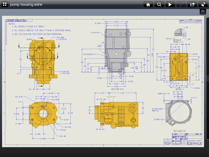

Save the zonal section view in SOLIDWORKS and then in eDrawings select the View Orientation button and choose the saved view.

You can also make custom configurations of all of your parts or subassemblies and have one specific for the Envelop setting. When you save section views with intersection zones or create model break views in SOLIDWORKS software, you can now see those views in eDrawings 2016. So there you have a quick step process for making items show up as phantom lines in a drawing view. The result is that I can now see all items that I selected as an Envelope in the Assembly Model as phantom line font in the view: I am choosing an Isometric view and Right Mouse Clicking on the view itself to access the Properties of this view:įrom here I can turn on the view option to show this as an Envelope: Next is the process of making a drawing and placing a view of this assembly. Also a small envelope icon can be seen here in the FM tree: Next, I can see that these items show up as transparent, a setting that can be modified in Tools, Options, System Options, Colors, Envelopes. I can then turn on the Envelope option for all of these components at one time: Next I select a few items from the view or from the FeatureManager Design Tree and access the shortcut from the pop up bar called Component Properties: To do this, I must first open the assembly file. For example, I have a top level assembly and I want to make 3 or 4 parts show up as an Envelope in the drawing view so that I can see them, but they aren't taking away from the rest of the drawing components. The process for this is really quite simple in SOLIDWORKS. Recently I was asked a question about showing some parts in an assembly drawing as "phantom" edges to be able to reference the components, but not have to show them as solid edge lines.


 0 kommentar(er)
